Applications in Imaging Optics
Oleophobic refers to the physical property of a molecule that repels oil. Fluorocarbons are deposited to the substrate to create a monolayer that repels oil and water. The additional benefit of evaporative oleophobic treatments is also hydrophobicity or inherent water-shedding capabilities. This inherent benefit is true of all evaporative oleophobic treatments, but not necessarily inherent in all hydrophobic treatments. The key differentiator between oleophobic and hydrophobic treatments is measured through contact angle and surface energy. Oleophobic treatments typically have a contact angle of 105-120° as measured with a goniometer, whereas hydrophobic coatings typically have a contact angle of ≤95° (contact Sunex for information on hydrophobic coatings with improved contact angles).
Currently hydrophobic and oleophobic coatings are very widely used. Among the most prevalent users of this coating technology are the consumer device industry in touch screen displays. The automotive industry is a slow adapter to this technology as it is more cost-sensitive, however, this technology is beginning to trickle into automotive rearview and surround-view cameras and cockpit displays.
The medical imaging field is beginning to utilize hydrophobic and oleophobic coatings. An example would be the use of these coatings on endoscope lens ends. Endoscopic lenses obviously see a great deal of liquids and oils during their use, and having an oleophobic coating on the ends of these lenses has been proven to help physicians.
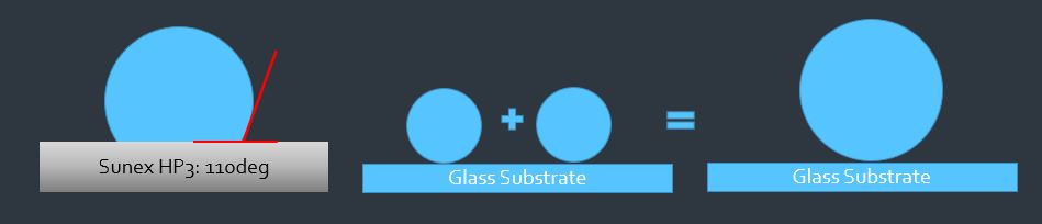
How Hydrophobic (HP3) Coatings Work
- Droplets collide, coalesce, become heavy and fall down
- Oleophobic
- Self Cleaning Feature
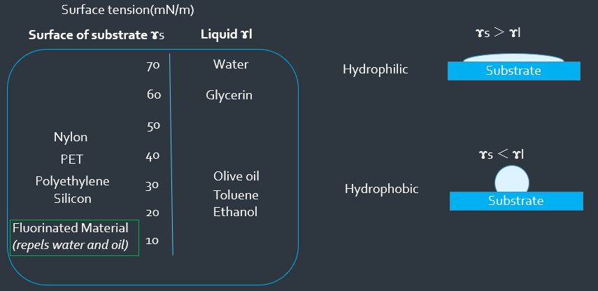
Why HP3 Coatings Work
A coating is described as hydrophobic when the surface tension of the applied liquid is greater than that of the substrate; in reverse, hydrophilic occurs at a state where the surface tension of the applied liquid is less than that of the substrate. Hydrophilic coatings are often applied on the inside (L1S2, the backside of the first lens element) to ensure any moisture spreads out to a thin film and does not bead up. The result is a layer of condensed water that remains clear, with no (or less) image disturbance. In comparison, hydrophobic coating repels water droplets from the surface allowing rain to run off the lens outer (L1S1) surface.
Fluorinated materials repel both water and oil.
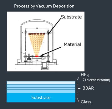
Hydrophobic Deposition Process
Currently, oleophobic and hydrophobic coatings are applied through vacuum and/or vapor deposition processes. Vacuum deposition of oleophobic and hydrophobic materials occurs in vacuum pumped chambers where an energy source (typically an electron beam) vaporizes a specific dielectric material that vacuum seals to the substrate outer layer.
Once the appropriate thickness of dielectric material is deposited to the substrate the pocket of dielectric material is then shut, and the hydrophobic material rotates into place and is vaporized. While airborne the evaporated material will create a permanent chemical bond with the already deposited dielectric.
Due to the thin nature of the coating, there is negligible effect to the optical properties of the substrate.
Hydrophobic Coating Characterization: Contact Angle Measurement
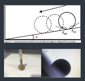
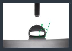
The simplest way to measure the efficiency of an oleophobic or hydrophobic coating is through the use of a goniometer which is an instrument that measures the contact angle of a drop of liquid. The contact angle of a drop of liquid can be measured by producing a drop of liquid on a solid. The angle formed between the solid/liquid interface and the liquid/vapor interface is referred to as the contact angle. The most widely-accepted method for measurement involves looking at the profile of the drop and measuring two-dimensionally the angle at the three-phase line as shown in the graphic.
Hydrophobic Coating Characterization: Roll-off Volume
This test is used to determine the droplet volume that will cause three droplets (of a particular mixed solution) to roll off the surface. A sample test procedure is outlined below:
- Mixed solution: Reagent A: Reagent B =1:2
- Reagent A: Mixture of 5g A1 ultrafine test dust + deionized water
- Reagent B: Mixture of NaCl + CaCl2 + NaHCO3 + H2O
- Lens is mounted on a 45 incline
- Droplets of mixed solution are placed on the lens surface
- Test criteria: What is the droplet volume when 3 droplets roll-off the surface?
- Test result:
- 5ml droplet rolled-off surface
- 4ml droplet did not roll off the surface